StruBIM Steel (Free Launch Edition)

StruBIM Steel (Free Launch Edition) is a program developed for the creation and maintenance of BIM models for structural steel detailing.
This program allows users to create a precise BIM model that includes the necessary elements (sections, plates, bolts, butt welds and anchorage) to define the structure. For the results output the program provides shop drawings in DSTV format.
Free Launch Edition
Although we are very proud of our new "StruBIM Steel" program, we believe that we still have to incorporate some features, as well as enrich the library of predefined joints, to fully satisfy its users.
For this reason, and because we believe that allowing users to use the program in its early stages of development will allow us to better understand their needs, we have published this launch version.
StruBIM Steel (Free Launch Edition) is a free version, with no expiry date and without limitations. It can be used professionally and will not disappear when the commercial version of the program is published.
At that time, users can choose to purchase the commercial version, which will allow them to continue to work on projects created with the release version, or to continue working for free with the launch version.
The new features that are incorporated into the program after the commercial version is published will not be incorporated in the launch version, but it can continue to be used for free.
We appreciate the interest shown in this program and the trust placed in our company.
Getting started
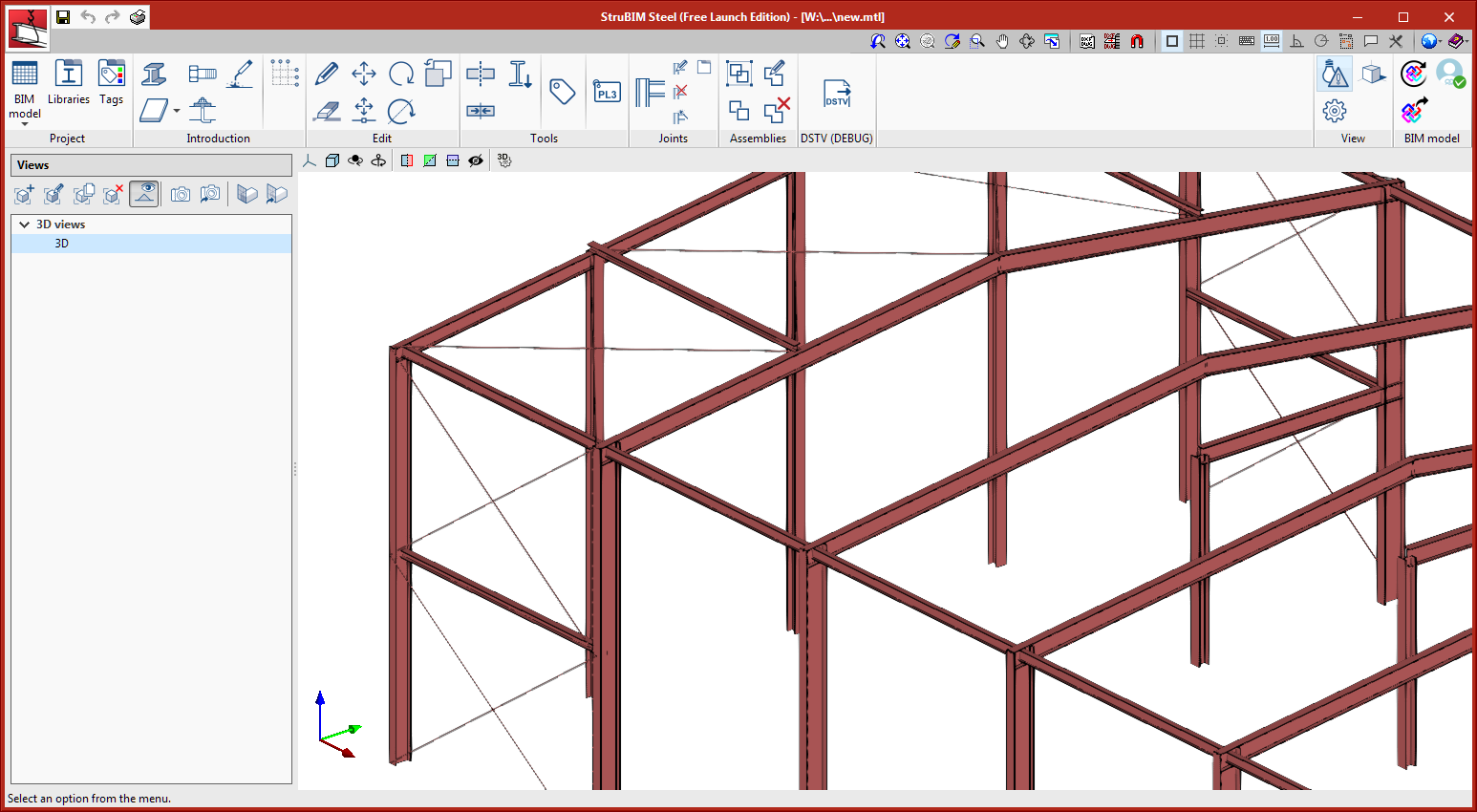
StruBIM Steel is a program integrated into the Open BIM workflow via the BIMserver.center platform. This program imports the steel sections from the IFCs of the BIM project, selected by the user. As well as offering the ability to import the sections from previously defined structures, the program includes the tools required to define a structure with certain ease.
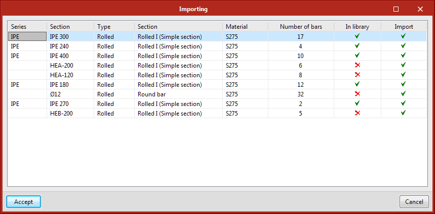
During the import, the program detects the different types of sections defined in the IFC and offers the option to import them or not, by clicking on the cell in the"Import" column. The "In library" column indicates whether the section is defined in the section library. If the section is defined parametrically in the IFC, the program will import it even if that type of section is not in the library.
Work environment
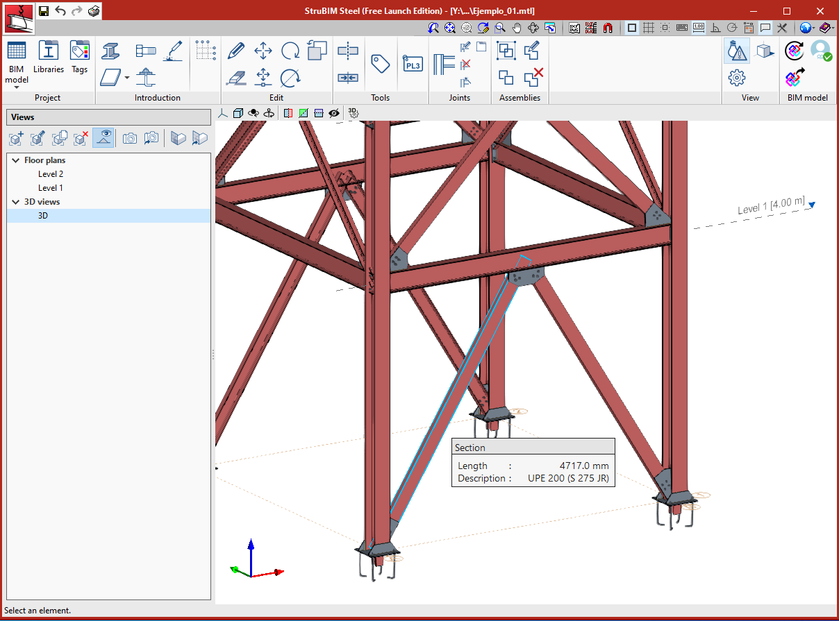
The program offers a 3D work environment with a detailed representation of the elements.
The toolbar is located at the top.
The view management is located on the left.
Toolbar
The toolbar has a number of utilities organised into different groups:
Project
- BIM model
In "BIM model" we can find the database of the different types of elements defined in the job. - Libraries
From "Libraries" the materials, section, bolt and anchor libraries of the job can be managed. - Tags
The management of the visibility and snap of the elements is carried out through tags assigned to the different elements. From this option it is possible to define the list of tags in the job.
Introduction
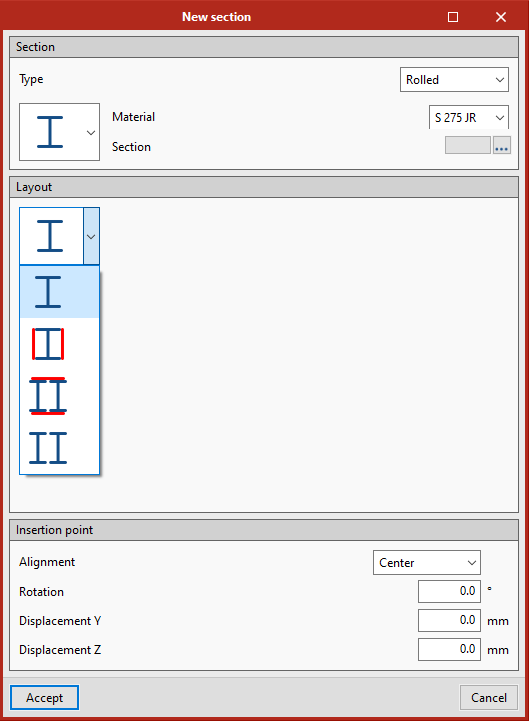
- Section
Allows a section to be introduced. - Plate
Allows a plate to be introduced, or a polygonal plate by indicating a selection of points or a circular plate by indicating the position of the centre and the radius. - Bolt
Allows a bolt to be introduced. - Anchorage
Allows an anchor to be introduced. - Welds
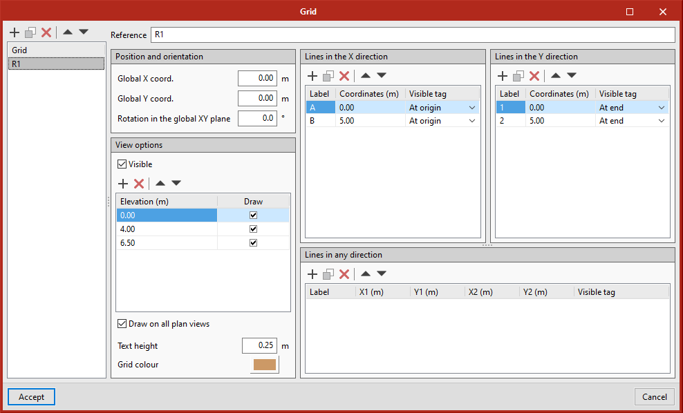
Allows a butt weld to be introduced. - Grid
Allows reference grids to be defined. One or more grids can be defined, composed of lines in the X direction, in the Y direction or in any direction. The grid can be made visible at different elevations.
Edit
In this section the edit tools for the elements can be found. These tools are shared with the rest of the programs:
- Edit
- Delete
- Move a group of elements
- Rotate a group of elements
- Rotate about an axis defined by two points
Given a selection of elements, the user can define, by using two points, the axis on which they wish to rotate the elements and the angle of rotation. - Copy
Tools
- Divide
This tool allows users to divide a section by a point on its definition axis. - Join
This tool allows users to join two or more sections that are aligned. The resulting section will have the section of the first selected section. - Assign tags
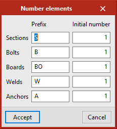
This tool allows users to assign tags to the elements. - Number elements
This tool allows users to automatically assign the reference of the elements. The same reference will be assigned to identical elements.
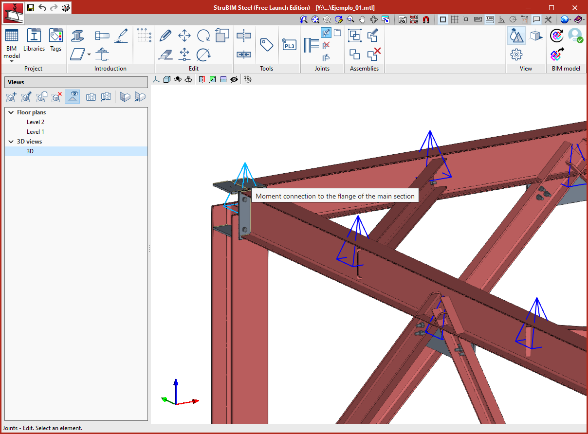
Joints
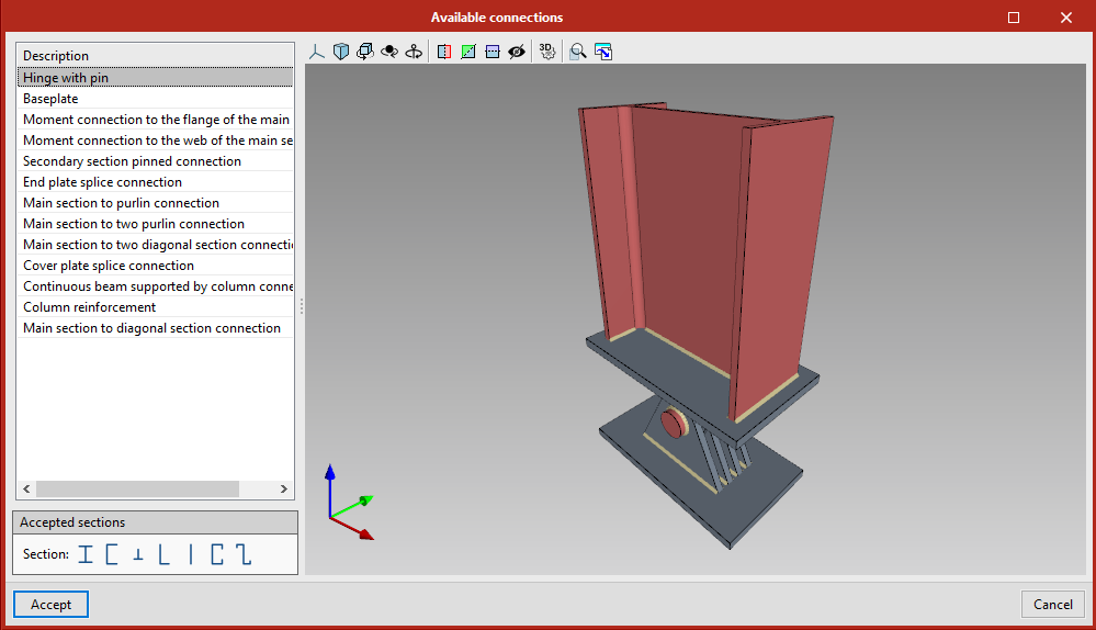
- Select connection
This tool opens a list of predefined connections that can be used. In the "Accepted sections" field, the different types of section to which each of the available connections could be applied are shown. - Edit
Allows users to access the edit window of a connection by clicking on the representative pyramid. - Delete
Deletes a connection. - Select connection based on sections
This tool indicates which connections are applicable to a selection of sections. - Library
Assemblies
- Assign
This tool allows users to group elements that form a single element or a structural component. - Ungroup
This tool allows users to ungroup the elements that form an element. - Edit
This tool allows the data of an element to be edited. - Delete
This tool allows elements to be deleted.
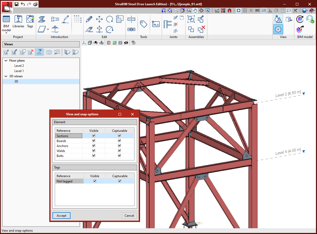
View
- Show/Hide warnings
- View and snap options
From this tool users can manage the visibility and the snap of the elements, by types of element or by tags.
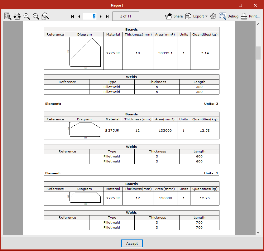
Export
The program exports the numerical control files in DSTV format for sections and plates. These files are saved together with the IFC file in the project directory and in BIMserver.center. It also generates a quantities report of the sections, plates, bolts, welds and anchors that form the elements.
Tel. USA (+1) 202 569 8902 // UK (+44) 20 3608 1448 // Spain (+34) 965 922 550 - Fax (+34) 965 124 950